3.5 KiB
| title | date | draft | summary | tags | series | math | |||
|---|---|---|---|---|---|---|---|---|---|
| Graphics Dump: Improving debug cubes | 2023-07-03 | false | When working on my engine, I wanted to clean up my debug gizmos a bit. The first thing to tackle is drawing bounding boxes! |
|
|
true |
When writing debug graphics, one of the most common shapes you draw are cubes. They usually represent bounding boxes, but I think they're really versatile. I'll be showcasing a way you can draw prettier debug boxes. Normally if you try to render a cube and only draw the wireframe, you end up with something like this:
{{< three-scene "scene.js" "scene" >}}
The diagonal lines are unnecessary and add visual noise. That's something you typically want to avoid, especially when in a debug view where the screen is already packed. However, I found a pretty neat trick for removing these without having to change the vertex data. I don't remember if I made this up originally or found it somewhere else, some precursory searches didn't turn up much.
Let's start by breaking it down to one face, in two dimensions:
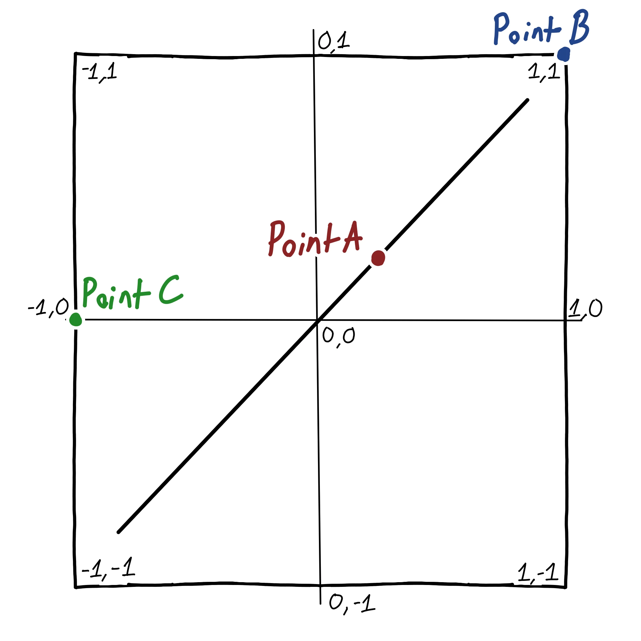
Point A (~0.25, ~0.25) has one component at the maximum, on the digonal. Point B (1, 1) has two components at the maximums because it's situated in the corner. Point C (-1, 0) is on the left side. We want to filter out A, but keep B and C since those make up the outer edges and corners. Basically, we need it to be on one or more maximums and if they are in between (like 0.5) then it needs to go.
In real GLSL, it would look something like this:
bool is_x_okay = abs(position.x) != 1.0;
bool is_y_okay = abs(position.y) != 1.0;
bool is_z_okay = abs(position.z) != 1.0;

int num_components = 0;
if (is_x_okay) {
    num_components += 1;
}
if (is_y_okay) {
    num_components += 1;
}
if(is_z_okay) {
    num_components += 1;
}

if (num_components < 2) {
    outColor = color;
} else {
    discard;
}
This is pretty disgusting, not only for the programmer but likely for the poor GPU too. Luckily, GLSL has all of the tools necessary to write this more compactly. A better version could be written like this:
void main() {
    if (length(vec3(notEqual(abs(position), vec3(1.0)))) > 1.0) {
        discard;
    } else {
        gl_FragColor = vec4(1, 0, 0, 1);
    }
}
Let's break this down, first we can simplify the many equality checks in the beginning with notEqual:
notEqual(abs(inPosition), vec3(1.0))
This is component-wise, so it has the same exact meaning as before. We want to call length on this, hence the vec3 cast. Why do we do a length cast? It's the easiest way to detect how many booleans are true, I'm not sure of a better way. For example:
(1, 0, 0)has a length of 1.(1, 1, 0)has a length of\sqrt{2}.(1, 1, 1)has a lenth of\sqrt{3}.
Hence, if we want to check if 0 or 1 components (but not more) we want a length less than 1. And here is the result:
{{< include-shader "wireframe.frag.glsl" "wire-frag" >}} {{< include-shader "wireframe.vert.glsl" "wire-vert" >}} {{< three-scene "scene2.js" "scene2" >}}
Since this is using GL_LINES (or your API equivalent) you can use the line width - if supported by your GPU - to modify how the lines look. Is this is a little convoluted? Maybe, but I like how it's all neatly integrated into just the fragment stage. I think this is good enough for debug purposes at least.